Nvidia’s RTX 5090 power connectors are melting
Nvidia’s RTX 5090 power connectors are melting
www.theverge.com Nvidia’s RTX 5090 power connectors are melting
The 12VHPWR power cable is still causing issues.
Nvidia’s RTX 5090 power connectors are melting
The 12VHPWR power cable is still causing issues.
Copying over my comment from elsewhere:
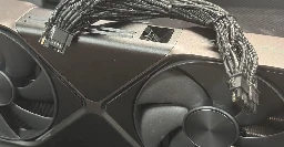
The person on reddit used a third party cable instead of the one supplied with the device.
https://www.reddit.com/r/nvidia/comments/1ilhfk0/rtx_5090fe_molten_12vhpwr/
It melted on both sides (PSU and GPU), which indicates it was probably the cable being the issue.
12VHPWR is a fucking mess, so please don't tempt fate with your expensive purchase.
Interesting that it lasted two years with their 4090 with no ill effects. Even though the 5090 is higher power draw, I would suspect the contact resistance of the cable was causing heating even before, just not enough to smell or deform the connectors.
It's only one wire in the cable, and it's not the wire, but it looks like the pin, or possibly the crimp point on the female pin.
So a few possibilities:
This is why I don't feel too strongly about people that buy first-batch hardware. They're the QC for the rest of us!
Not even first batch as far as this connector goes. This has been an issue ever since this connector was released on the 40 series cards in 2022.
The sensible thing would've been to just rollback to the standard 8-pin PCIe power connector that has been reliable for many years. I guess requiring 4 of these for 600 watts would highlight how ridiculous the power draw of the 5090 is.
Instead they made small iterations to this 12VHPWR connector (changing sense pin lengths and other small adjustments) and they're letting their paying customers test the new iteration with the 50 series.
Admit that 12VHPWR is bullshit and revert to 8-pin. Come up with a working solution or just stick with 8-pin long-term.
I guess requiring 4 of these for 600 watts would highlight how ridiculous the power draw of the 5090 is.
I like the way you think.
Even two of the 12VHP connectors would be better.
Ngl I kinda think anyone who buys a current gen, top of the line GPU is a bit of a chump and has been for over a decade.
They just don't make that big of a difference.
I mean… I jumped on a 3080FE several years ago near release time because
Its fine. Nvidia is introducing these new quick disconnects:
They are?
You'd think they'd learn after like the 4th or maybe 5th time. I've honestly lost count.
Why not just use a connector that is designed for this much and is already cheap and easily available.
One plug for the GPU one for everything else. I give it 5 years until this is reality lmao
That's designed to work at 120V. The PSU-GPU connector is 12V. I don't know if it'd actually work well -- like, the contacts would have a tenth the conductive capacity, I guess.
Honestly, the main standardized 12V DC connector that I can think of that we use is the car cigarette lighter, which I don't think normally moves anything like that much power and is terrible, doesn't lock into place, was never intended as a power source. I would like a 12V locking connector that can move a lot of juice.
https://www.amazon.com/JacobsParts-Cigarette-Lighter-Adapter-Electronics/dp/B012UV3QI4
Input Voltage: 12 Volts
Amperage: 2 Amps
That particular cable and plug will handle 24 watts. I know that you can get higher power ones -- I had to go out of my way to find one that could do 100W.
My guess is that the 12V problem will never really be addressed and we'll just go to USB-C PD at up to 50.9V for our DC power connector standard. Which I guess works too as long as the amperage doesn't get too high, but that won't be enough to feed a current high-end Nvidia GPU.
Maybe have, like, multiple USB-C PD connectors in parallel. Three should do it.
Sitting on my 7900xtx eating popcorn.